Building a CoverFlow visualization using Quartz Composer
I have been playing around with Quartz Composer (included as part of the Developer tools installation on Mac OSX) for almost a year. It’s a great tool for creating screen savers, music visualizations and also for quick prototyping of some visual concepts. I personally find the patch-based approach to solving problems quite refreshing and offers a different perspective to looking at complex problems. It is very much like programming but with functional blocks (called patches) rather than real code.
Understanding the CoverFlow visualization
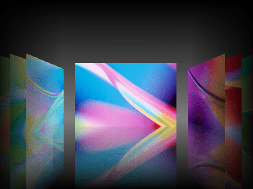
Before I talk about how we can pull this off in QC, it would be good to take a quick look at the building blocks of CoverFlow. We all have seen it before, but it would be good to analyze it from the point of view of a QC composition:
-
We have a set of tiles placed left to right with some gap between tiles. The selected tile is in the center of the viewport with some additional gap between the center tile and the adjacent tiles.
-
A tile can be in one of three orientations: tilted on left, straight center, tilted on right (as shown in the picture above)
-
Each tile has a reflection at the bottom, fading into the background
-
As the selected tile changes, every item does a sliding+rotating animation to take up a new position and orientation
-
A few polishing touches include a dark vertical-gradient as background and a horizontal gradient that fades off the edges. The edge-fading gradient (called a vignette) is needed to give a lighting effect on the center, selected tile.
Decomposing the Quartz composition!
Quartz Composer is a patch-based programming tool, which means we will have to think in terms of functional blocks or patches that do some simple operation. A patch has some inputs and outputs. Your job is to provide proper inputs and use the outputs to feed other patches. You can also encapsulate a set of patches into a Macro Patch, which provides a simpler abstraction over some complex operation. The Macro Patch can be used like regular patches, possibly having its own inputs and outputs.
Connecting these patches together we can create visualizations. I like to think of this as circuit-board design, where we take a bunch of ICs (Integrated Chips) and design a micro-processor. The Quartz Composer provides a way to design a micro-processors that can generate visualizations. The figure below shows a part of the CoverFlow composition.
The CoverFlow composition is built up of a few Macro Patches that are layered to create the visualization. Lets understand this from the bottom-up.
[A] A CoverFlow tile
At the bottom of the stack is the notion of a single CoverFlow tile. This tile provides the base properties that will be controlled from higher level patches. From our earlier analysis, we know we need the following capabilities:
- Reflection
- Positioning on the X-axis
- Y-Rotation to show the tilt
- An Image that acts as the texture for the tile and the reflection
A Sprite patch provides all of these capabilities, except for the reflection. To get the reflection we use an extra Sprite and apply an inverted version of the supplied Image. We finally apply a gradient mask to obtain the fading reflection effect. The mask gradient is from 85% transparency to 100% transparency (fading into background). To make it easy, I have encapsulated all of these patches into a Macro Patch called “Reflected Tile”. The following figure shows the “Reflected Tile” patch. Click on it for a full-size image.
[
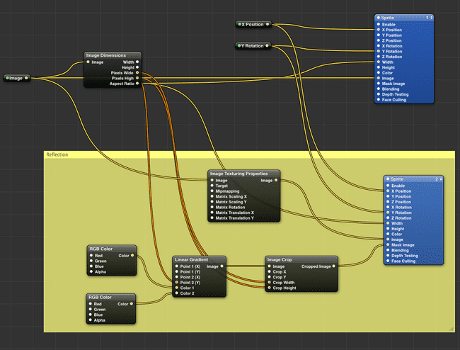
One thing you will notice is that I am exposing the “Image”, “X Position” and “Y Rotation” as inputs (shown with light-green dots) into the “Reflected Tile” Patch. These will be set from a higher level patch, the “CoverFlow Tile” patch, which is yet another Macro Patch.
The “CoverFlow Tile” Patch
This patch represents a single CoverFlow Tile.
[
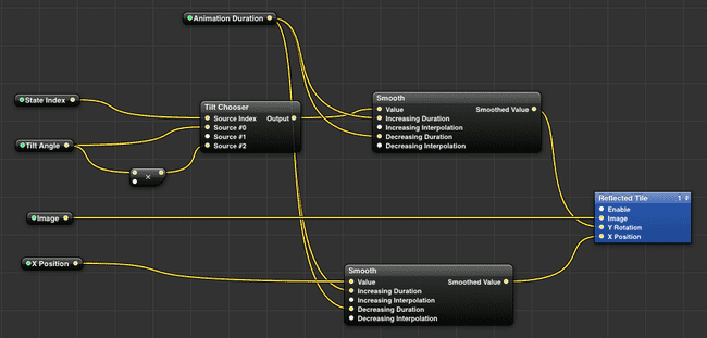
This patch provides an numbered input called “State Index” that can be either 0,1,2, representing the three different orientations: left tilted, straight-center, right tilted respectively. Depending on the state we apply the correct “Tilt Angle”. The left tilt is positive and the right tilt is negative. The negative tilt is applied with a simple Math patch that multiplies the “Tilt Angle” by –1. This patch wraps the Reflected Tile patch and also exposes the “Y Rotation” input on the Reflected Tile patch as “Tilt Angle”. We have also applied a Smooth patch for the “X Position” and the “Y Rotation” to animate the position and orientation changes on the tile. The default animation-time is 0.5 seconds, and can be controlled with the “Animation Duration” input on the CoverFlow Tile patch.
[B] A list of CoverFlow Tiles
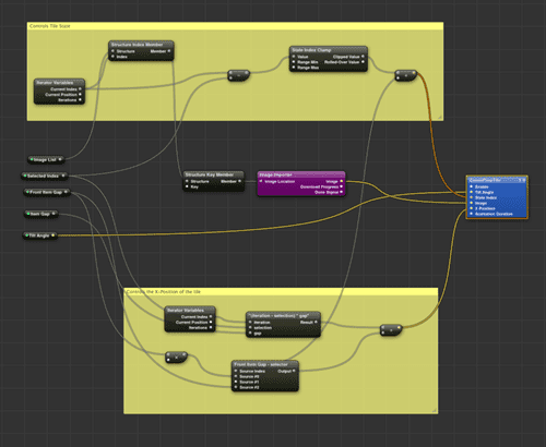
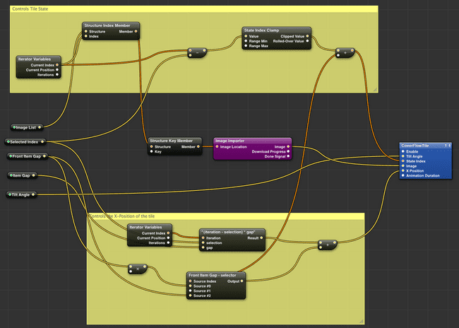
With the basic tile patches in place, we are now ready to tackle the display of a set of tiles. Each tile will be rendered using the “CoverFlow Tile” patch but needs to be positioned and oriented depending on a “Selected Index”. The Selected Index is exposed as input into the Iterator patch, a stock Macro Patch provided within Quartz Composer. The Selection Index divides the tiles into 3 sets: the selected tile (center tile), the tiles to the left and the tiles to the right. The X Position and Tilt Angle of each tile is entirely driven by the Selected Index and the “Current Index” of the Iterator patch.
To obtain the “Current Index” within the Iterator Macro Patch, we use the standard Iterator Variables patch provided within QC. Using the Selected Index and the Current Index of the Iterator, we can determine the “State Index” of the tile. Recall that we have 3 states for each tile, that specify the orientation of the tile. The state of the tile is controlled by this State Index.
The X Position of the tile requires more calculation as we use the “Item Gap” and the “Front Item Gap” inputs to correctly position the tile. Note that the Item Gap and Front Item Gap is only applied to the left and right tiles. The center tile is unaffected by these inputs. The figure below shows the complete wiring of the “Tile Iterator” patch. The value of the X Position is governed by the fact that we use a 3D co-ordinate system where the origin is in the center of the screen. The X values decrease to the left of the origin and increase to the right of the origin.
[
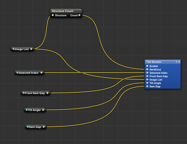
The “Image List” input is the set of the images over which the Iterator patch iterates. This is fed as input from higher level patch that represents our entire coverflow visualization. This patch is aptly called the “CoverFlow Control” patch, as shown in the figure below. Note that all the necessary inputs are exposed on this patch.
[
[C] Providing Keyboard input for selection
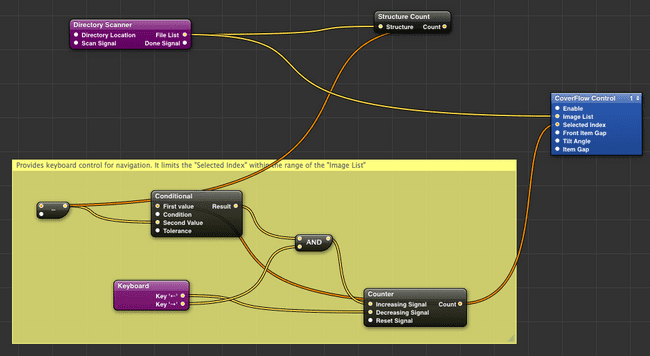
Of course, no CoverFlow control is void of user interaction! Thus our composition dutifully provides some control using keyboard input. In Quartz Composer the Keyboard patch can be used to detect keyboard input. A set of keys can be configured in the settings for the Keyboard patch, which will generate a signal (a momentary boolean value) whenever that key is hit. In our case, we use the Left/Right arrow keys for changing the Selected Index of the CoverFlow Control.
The Keyboard generated signals are fed into a Counter patch that increments or decrements a count. The Left arrow decrements and the Right arrow increments. The output of the Counter acts as input to the Selected Index of the CoverFlow Control patch. We also use a Conditional patch to ensure that the count generated by the Counter is always within the index range [0, n-1] of the Image List . A Directory Scanner patch provides the location that contains all the images. This patch creates a Structure (an array of objects) that then becomes the Image List input to the CoverFlow Control patch.
With this setup we now have a way to drive the CoverFlow visualization. The figure below shows the wiring for the keyboard input.
[
Final polishing
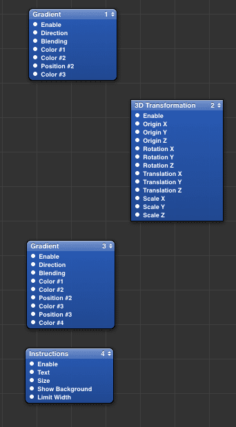
The final polish to this composition is done by applying a bunch of Gradient patches that generate the background and the fading edge effect (vignette) on the CoverFlow. We also wrap the previously described patch in section [C] inside a 3D Transformation. This is used to scale down the entire visualization and leave some room at the bottom to show keyboard-navigation instructions.
Quick video showing it in action
CoverFlow using Quartz Composer
Download
For exploring all the details about this composition you can download and peruse the .QTZ file:
Further Reading
- If you would like to dig deeper into Quartz Composer, I suggest reading the Quartz Composer User Guide
- Also look out for this book by the well known VJ Shakinda: Learning Quartz Composer
