

Genie Effect, the WPF way
I have been contemplating for many days about creating the Genie effect that you see in Mac OSX, when you minimize a window. It kind of creates a suction effect like a cloth being sucked into a vacuum cleaner. If you have a Mac, you would know. Unfortunately I don’t have a Mac, well not yet! So what better can I do to fill the void…what about creating the Genie Effect in WPF?
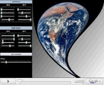
Before we go onto the boring parts of how this was done, have a look at the Video (about 5 mins) so you know what you are up for! You can also download the Demo. You will need .Net Framework 3.0+.
Dismantling the components
To understand what goes on here, let me show in XAML what the end result should look like.
<Page xmlns="http://schemas.microsoft.com/winfx/2006/xaml/presentation"
            xmlns:x="http://schemas.microsoft.com/winfx/2006/xaml">
    <Grid>
        <Path Stroke="Black"
                    StrokeThickness="1"
                    Data="M 100,100 C 100,200 400,300 400,400
                        M 600,100 C 600,200 500,300 500,400
                        M 100,100 L 600,100
                        M 400,400 L 500,400">
        </Path>

    </Grid>
</Page>
You can copy+paste it in XAMLPad / Kaxaml and it should look like:
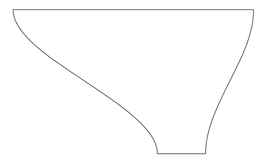
We have to create a surface like this in 3D so that it can be deformed. In fact the reason we are going to 3D is for the better control over deformations. Now if you look closely, our mesh is going to be defined by a curvy left edge and a curvy right edge. In more technical terms we have a Bezier curve for the left edge and another Bezier for the right edge. The rest of the mesh points will be interpolations between these two Beziers.
The best way to use a Bezier curve is to use its parametric form. Since we are using a cubic Bezier, we will have 4 control points. Each control point contributes to the curvature based on the Basis functions, which are also called the Bernstein polynomials. Ok, those were some loaded terms but it suffices to say that our Bezier will be defined by 4 control points that give it curvature. Each control point contributes based on a function as shown below:
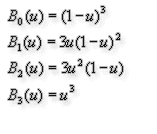
Since we have two Beziers we will use separate control points for each. So in all we will have 8 control points. The first and fourth control point of each Bezier are the start and end locations. The parameter u varies from 0 to 1 ( 0 <= u <= 1 ). At u=0, we are at the start of the curve and at u=1, we are the end of the curve. You can check that by substituting the values for u in the equations above. Using these equations we can get various points on the curve. Note that we need to apply these equations for each of the X, Y and Z components and get the Point3D that lies on the curve.
Once we have the curves, the rest of the mesh points are just a linear interpolation from one end of the curve to the other. With the mesh in place, we can now animate it by just manipulating the values of u for each Bezier
Links